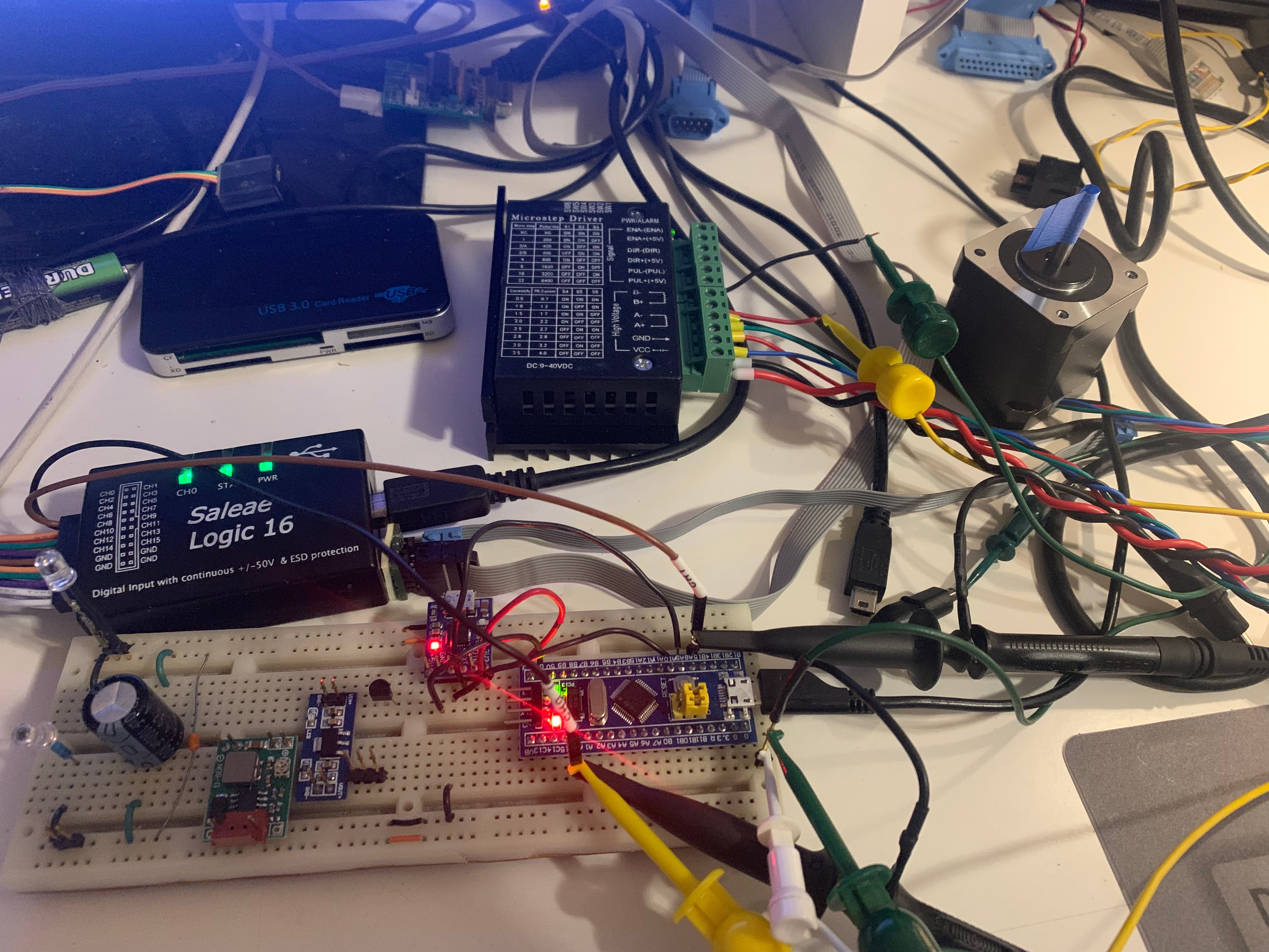
Received my ebay STM32F103C8 “Blue Pill” board today. It’s a really inexpensive $2 72Mhz ARM Cortex-M3 dev board that is also Arduino compatible. The Arduino Core is called STM32duino.
There is a 6 axis grbl version available. This requires the free Atollic TrueSTUDIO to compile the source code. So far no problems running it on the dev board. I find it to be a little bit slower than LPC1769/grbl-lpc version running laser grayscale raster image scanning. This is the firmware if you don’t want to compile your own version. The i/o pin mapping is found in the cpu_map.h file.
You can use these instructions on how to burn the grbl firmware. Just upload the above firmware file instead of the bootloader. You may need to install the STM32 virtual com port driver if you are running a older version of Windows.
Lightburn Laser software has no problem connecting and controlling the STM32/grbl version.
Single axis maximum step pulse rate is about 95khz.
Updated 4 axis firmware with increased buffer size. I changed the following config.h settings:
#define BLOCK_BUFFER_SIZE 254
#define SEGMENT_BUFFER_SIZE 15
This greatly improved the laser grayscale raster speed.
Same 4 axis firmware as above but with inverted PWM. The inverted PWM code update was from this STM32 fork by mstrens. Thanks!
After uploading new firmware, issue a $RST=* in the console. This will reset the boards eeprom and load the default grbl settings.

This is a logic analyzer screen shot capture of 4 axis simultaneous movement. The gcode command was g1x.2y.2z.2a.2f10000. The step pulse timing outputs are the same for each axis. I ran various simultaneous gcode move commands and the timing logic all look good. Different acceleration and step per mm settings were also tested.
Variable Laser PWM, M7, M8, M9 outputs work.

 Pinout diagram; courtesy of Rasmus Friis Kjeldsen:


Hi .
I tryed this grbl , and works , fine , but when i try t use it on laser , spondle output remain high , on my osciloscope , and doesnt triger low when no cuting is achived .
Do u know what i do bad ?
Thanks .
LikeLike
I made a firmware version with inverted PWM. You can download it on the same page. I didn’t do much testing so let me know if there is a issue.
LikeLike
Hi Jim , in the pre-compiled versions, what did you set the pwm frequency to?
LikeLike
I didn’t change any PWM setting. Have to look at the source code to see what the default was set at.
LikeLike
Hi Jim, Merry Christmas. I scoped it out and it’s 10kHz. Can you point me to where you made changes to invert the PWM?
LikeLike
I used this update. https://github.com/mstrens/grbl_6axis_on_stm32
LikeLike
The link to the firmware uploading instructions is broken, how can I burn this firmware using an FTDI module, I don’t have ST-Link programmer in hand.
Thank you
LikeLike
They change the site but the info will be in the forum located here
https://www.stm32duino.com
LikeLike
It’s located here now
https://github.com/stm32duino/wiki/wiki/Upload-methods
LikeLike
Thank you!
LikeLike
Hi Jim,
Does the 4th axis on this firmware linear or rotary ?!
LikeLike
You can use it for either. For rotary, it would be steps per degree instead of steps per mm
LikeLike
YOU ARE AWESOME JIM. THE WORLD NEEDS LOTS OF BLESSED PEOPLE LIKE U. THANK YOU SO MUCH FOR SHARING.
LikeLike
How do you recompile and export the hex file?
LikeLike
You need to install the TrueSTUDIO STM32 compiler in the link above. There is documentation on how to setup, compile and create the hex output code.
LikeLike
Hello, I’m having trouble changing the firmware settings and leaving the changes to the eeprom saved, whenever I restart STM32 the firmware settings return to the default losing the changes I made. How to fix this?
LikeLike
I don’t have that issue. Try another STM32 board. I’ve read there are now Chinese clones that are passed as the real deal. That may be the problem.
I retested and flashed the stm32grbl11_v2._invertPWM.hex firmware on my Blue Pill board and had no problems with saving settings. I reset, power off the board and all setting were saved.
LikeLike
You have the config.h for the 4 axis hex you shared? All things work fine except the single axis homing which is disabled. I tried doing my own compiling but I am having issues with probe always in the normally closed status. I am unable to figure out. Doing the $6=0 or $6=1 does nothing. The limits are good though. My compilation is responsive with $5=0/1. Also did the single axis homing no problem.
LikeLike
I haven’t used stm32/grbl in a very long time. ESP32/grbl was my choice on the last project needed to use grbl. More support and updates available now.
LikeLike
Hello.
I want to use this project on a CO2 laser with power suppy MYJG60W. Do you have any information how to wire up this kind of laser power supply to STM32? I mention that i want laser power to be controlled from LightBurn.
LikeLike
No info on that power supply. Many laser power supplies use a active low PWM input, sometimes called LO
LikeLike